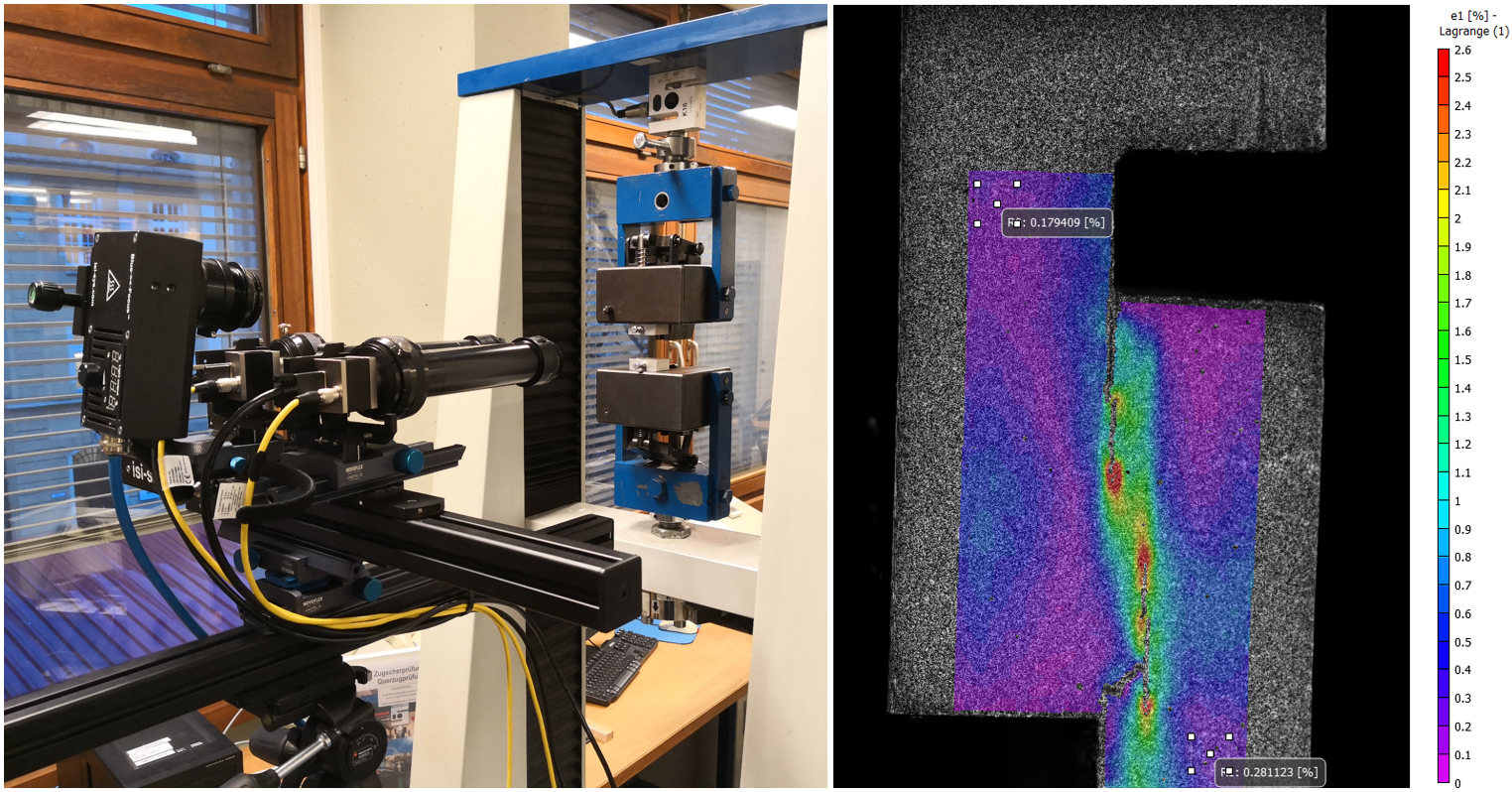
The new VIC-3D Educational (EDU) System from Correlated Solutions is a low-cost solution developed for academic institutions to assist in teaching the Digital Image Correlation technique to undergraduate and graduate students.
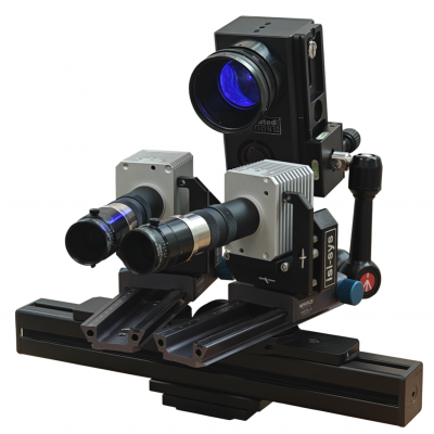
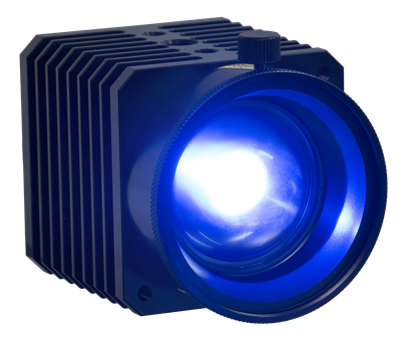
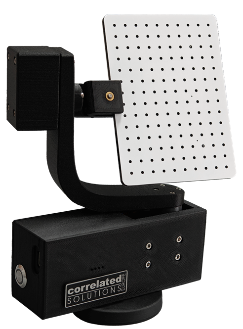
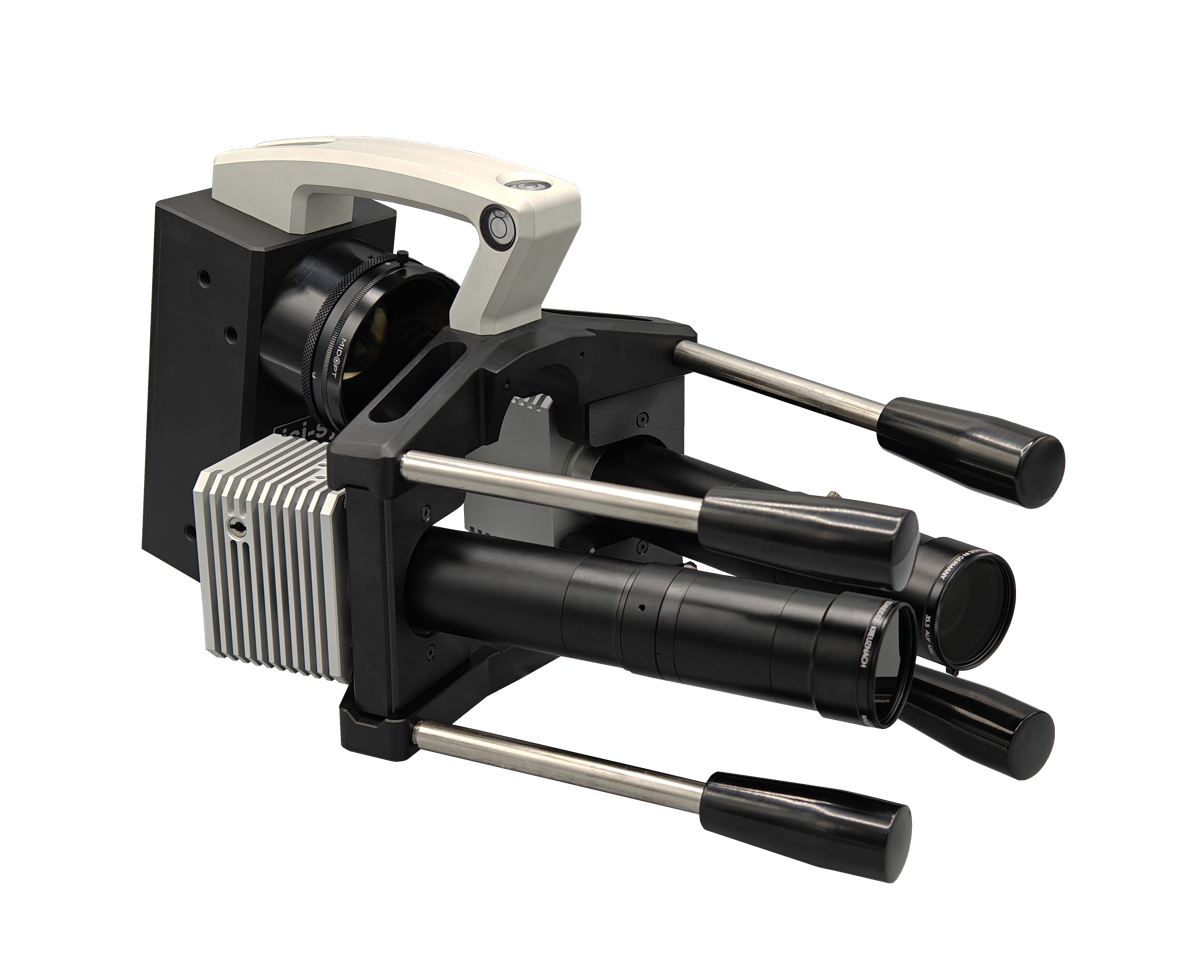
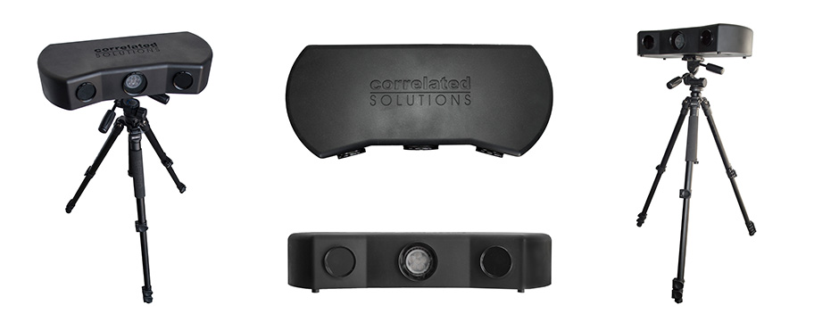
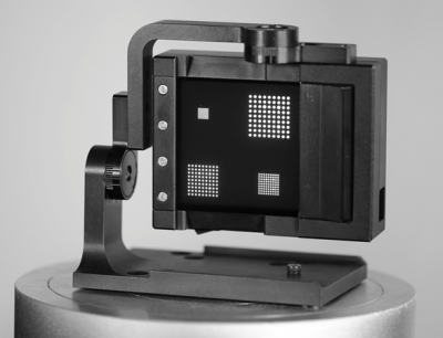
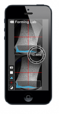
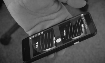
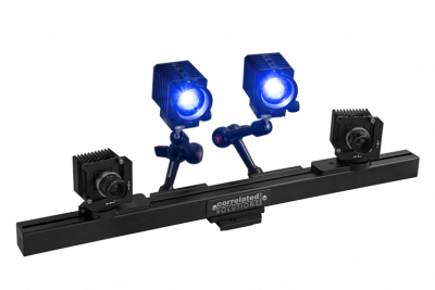
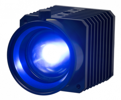
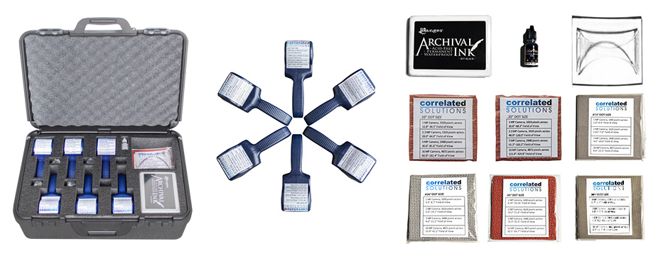
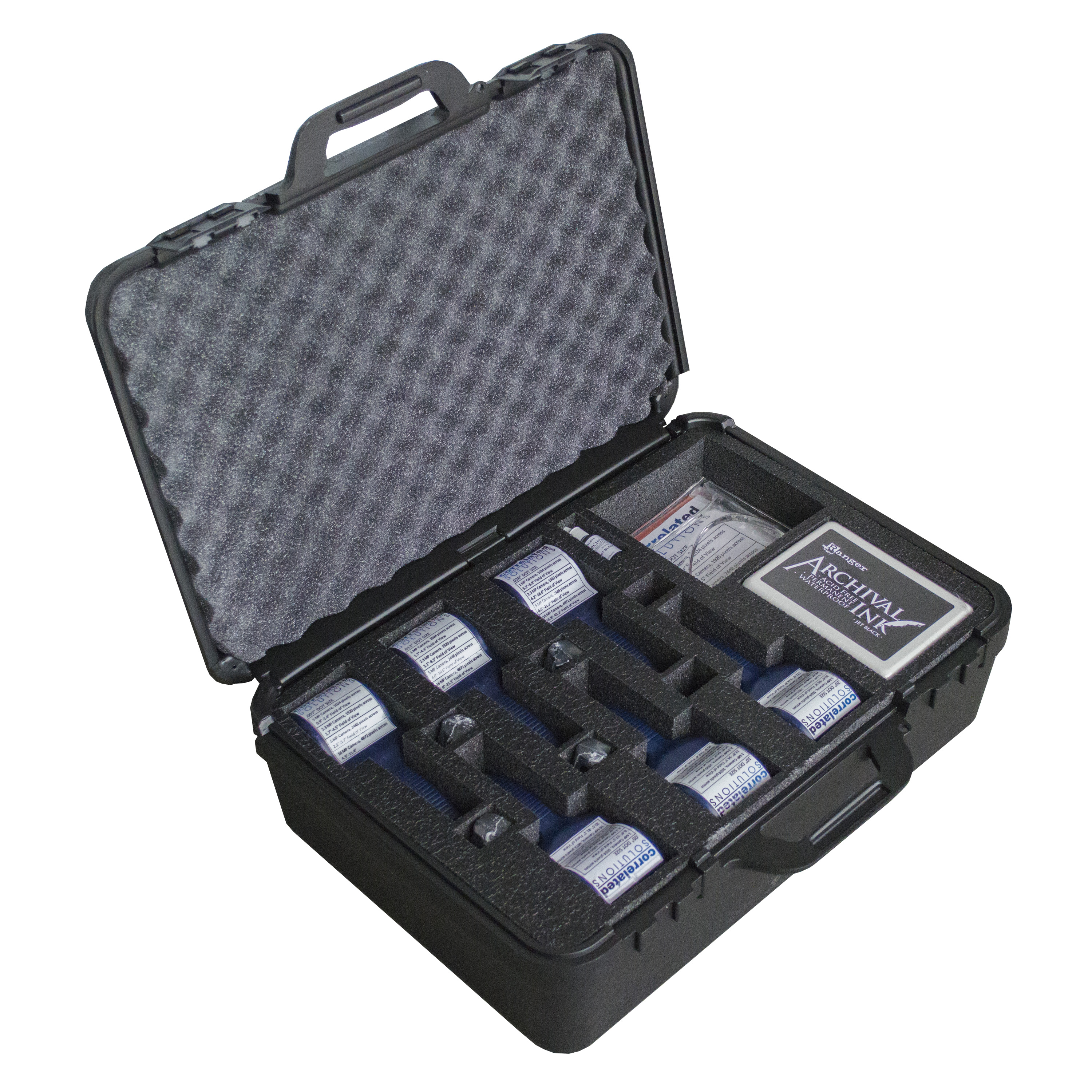
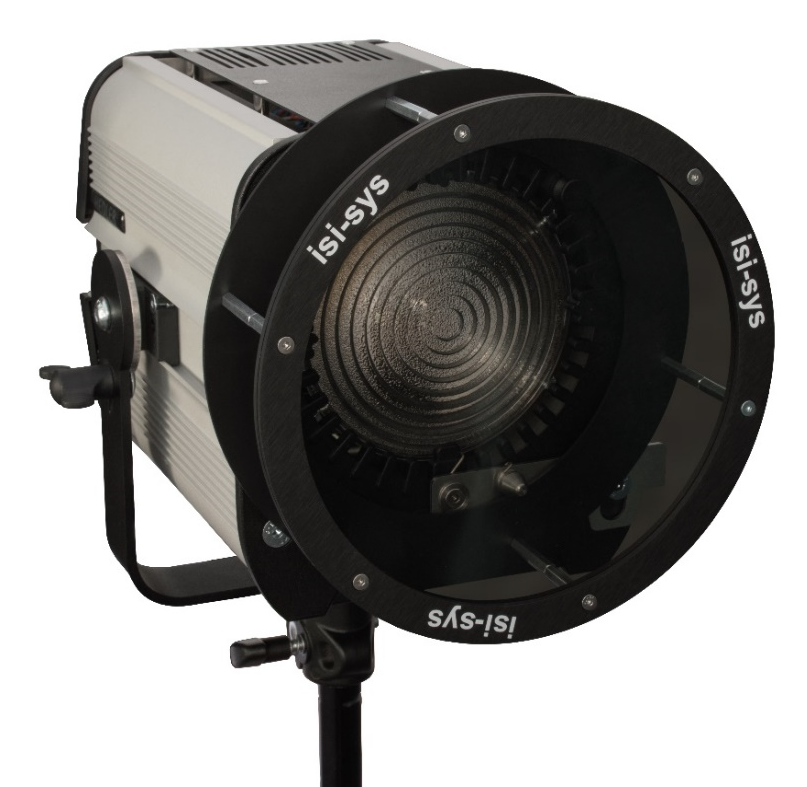
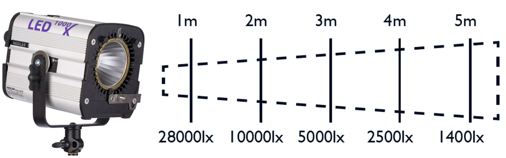
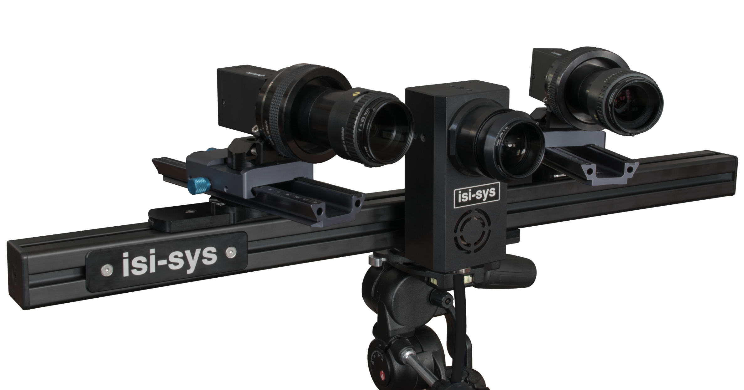
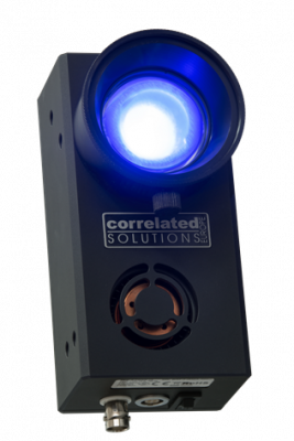
The VIC-3D EDU system utilizes the same accurate DIC algorithms found in the powerful VIC-3D software, while allowing users to acquire data quickly and easily. The system features a simplified setup, streamlined image acquisition, and ideal post-processing features. The stereo cameras are mounted inside a protective enclosure, which includes an integrated LED light source, a cooling fan, and an exterior USB & power connectors. The system also includes a tripod, tripod head, speckle roller, ink pad, calibration target, and a convenient carrying case.
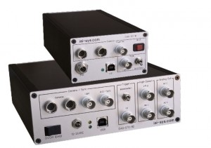
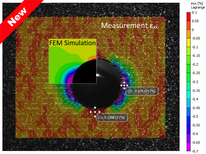
This product is the perfect addition to engineering courses such as solid mechanics, measurements, structures, automotive design, aerospace, safety, FEA validation, and many others. Furthermore, the VIC-3D EDU software has the ability to process images acquired from any VIC-3D EDU system, which allows users to share images not only across campus, but also with colleagues at other universities. The system simply requires a computer with one available USB3 port and one available power source. Whether you are teaching students new measurement techniques or validating FEA models, this system will surely enhance the quality of your department’s curriculum.
VIC-3D Educational System specifications:
| Camera Resolution |
1920 x 1200 (2.3 Megapixels) |
| Frame Rate |
20Hz live, .5Hz acquisition, 100 frames per capture |
| Exposure Time |
19µs – 1s |
| Field of View |
Fixed: 150 x 200mm |
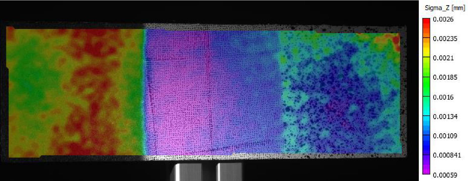
| Displacement Resolution |
In-plane: +/-2µm; Out-of-plane: +/-4µm |
| Strain Measurement Resolution |
50µε |
| Strain Measurement Range |
0.005% to >2000% |
| VIC-3D EDU Licenses |
Unlimited |
| Software Features |
3D displacements, strains, graphing tools, and much more |
For more information or a quotation please don’t hesitate to contact us on info@isi-sys.com or via phone: +49 561 739798–0.


 Further details: