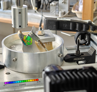
The video example shows a four point bending test setup for a metal beam with drilled holes (side view). The beam surface is measured by a VIC-3D Professional stereo system from below via a surface coated mirror. The measured principal strain are projected on the mirrored image of the sample surface. Measurement of 9/2023, University of Lübeck.
Material testing
Strain Gauge Comparison
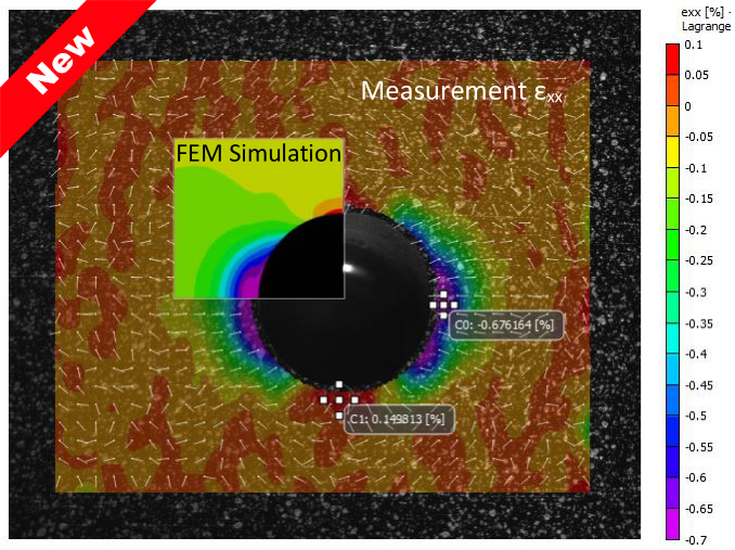
In this example a Vic-3D measurement with 5MP CMOS Camera was performed. The acryl specimen is fixed in a tensile testing machine. A strain gauge is attached at the back in combination with a SCAD 500 strain gauge amplifier. The output of the SCAD 500 was connected to the DAQ of the DIC system. The strain results are recorded parallel with the Vic-3D measurement and plotted in a diagram. The camera type is equipped with Sony 5Mpx Pregius sensor, 75 fps.
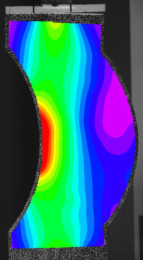
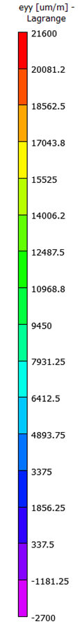
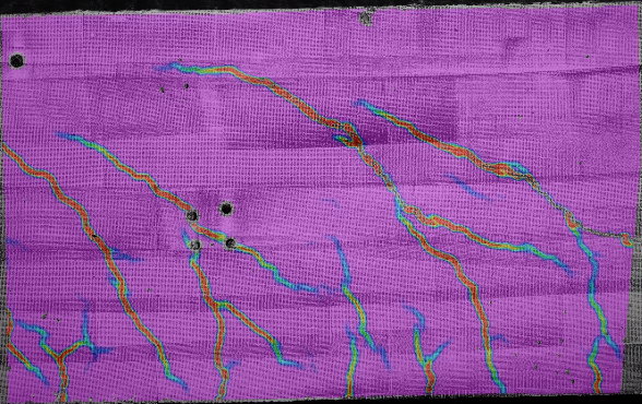
Image 1: Vic-3D measurement of the acryl specimen
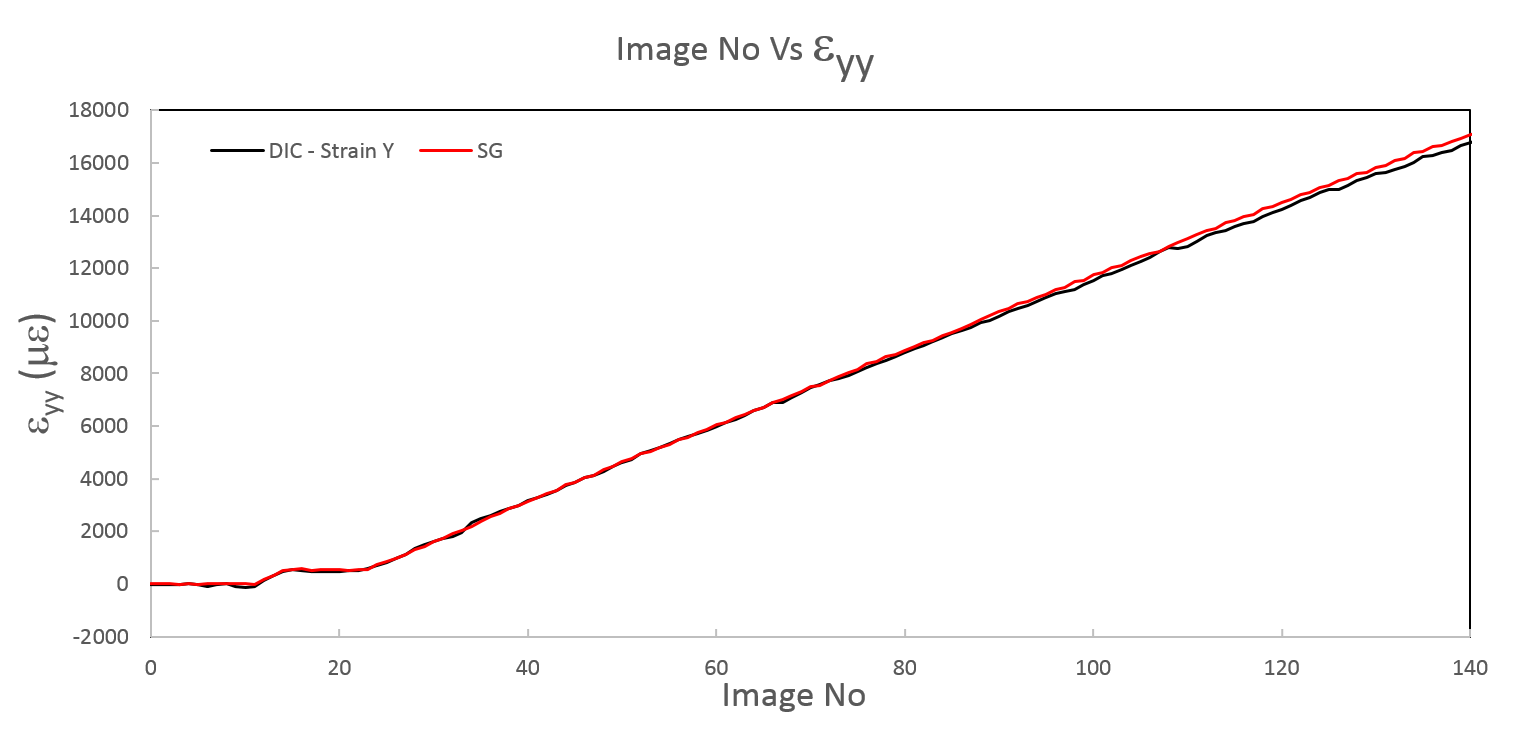
Image 2: Comparison of strain gauge data (red curve) and DIC Strain data (black curve)
The Vic-3D data match nearly perfect with the strain gauge data. Even at low strains the difference is less than 25 micro strain.
Strain Measurement — 2D Fatigue Test
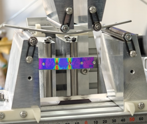
Results of a 2D fartigue test on a thick piece of notched steel. With the use of a 2,3MP camera and Vic-2D a high strain resolution of approximate 5–10 microstrain can be archieved.
The video shows the results of this fartigue test.
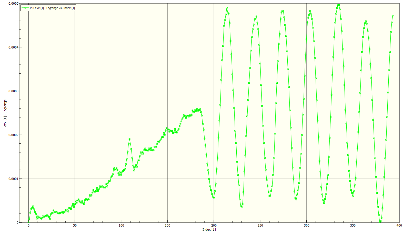
The graph demonstrates the bending load over time.
Strain measurement of a Cable Sheath
The video shows an experimental setup of a strain measurement with digital image correlation. A segment of a 3 mm wide cable insulation is loaded by a tensile machine until failure.