Digital Image Correlation
versatility, robustness, and ease of use
Digital Image Correlation (often referred to as “DIC”) is an easy-to-use optical method to measure deformation on an object’s surface. Digital Image Correlation has been proven over and over to be accurate when compared to valid FEA models. The DIC systems from Correlated Solutions utilize this advanced optical measurement technology.
Measurement Principle
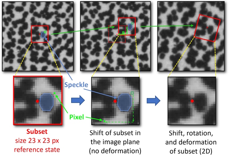
DIC measures the shape (3D only), motion/displacement and deformation of objects by tracking natural or artificial prepared speckle patterns visible on their surface. This is done in small regions, called subsets. Here a subset is highlighted in red for camera image section covering 23 x 23 pixels. The pixels are represented by the grey value squares (e. g. digitized with 8 bit resolution), of which one is selected and marked in the subset and images in green. The subsets are numerically represented by the pixel grey values and their distribution.
Correlation principle: The subsets change their positions and shapes relative to the reference state. The VIC software models this displacement transformation (subset shape function) to define the deformed subset and displacement for its center (red cross) with subpixel resolution (e. g. 0,01 px).

Stereo triangulation principle
The principle of 2D correlation is now combined with the principle of stereo triangulation using two cameras (images). The positions of the subset centers (point P) prepared on the object surface are determined by the intersection of the corresponding light rays in VIC-3D. This allows to determine the shape (x, y, z) of the object surface from each image pair captured simultaneously for each deformation state.
As mentioned above, 3D deformations (U, V, W) is analysed relative to a reference state, but now between two stereo image pairs for each state. When combined with shape information, surface strains can be derived from the tangential (inplane) deformation fraction of a local number of points P and their deformation P(U, V, W) values, in combination with user defined spatial and timed filters in VIC-3D. The lack of contour information is one of the main limitations and sources of error for 2D DIC.
What is required for a measurement?
Optoelectronics
(Stereo) System Mounting
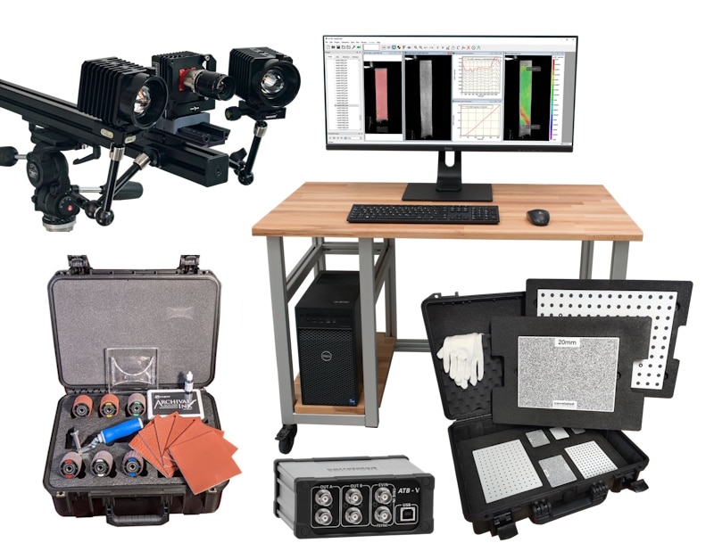
Desktop PC or Laptop with VIC Software
Trigger & Data Acquisition (DAQ)
Accessories