Flexible and Efficient: One sensor system for dynamic, thermal and vacuum loading.
Dynamic Loading
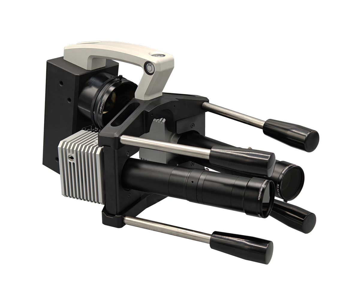
For the dynamic loading the piezoshaker excitation systems are designed by isi-sys. It consists of a Piezoshaker, amplifier and function generator. For a detailed description please refer to the report “Products / Piezoshaker Systems ”
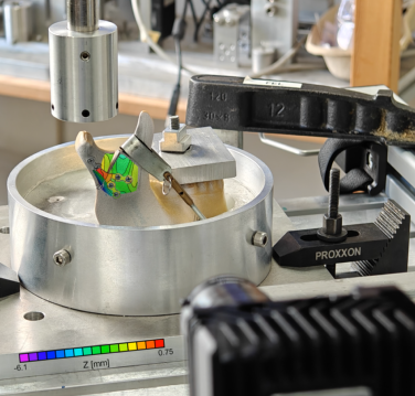
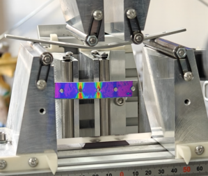
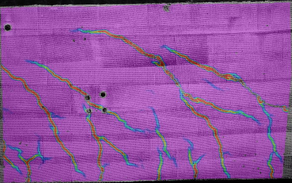
The video on the right shows the lamb waves, generated by the piezoshaker, that is attached at the bottom of the specimen. The waves travel across the object surface and excite the five local subsurface defects on the top. The local defects vibrate differently, depending on their local mechanical properties (stiffness). Only very little power of the piezoshaker is required, when the excitation frequency is close to the local defect resonance frequency. This principle is used in non-destructive testing for example, especially to locate delaminations in sandwich structures.
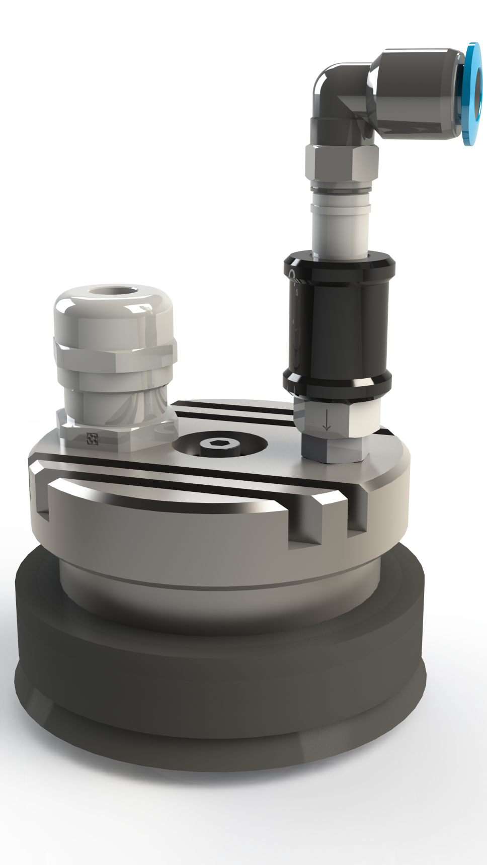
The Piezoshaker can be attached by vacuum to the object surface. The HVDA‑0–180 amplifier is especially design for isi-sys Piezoshakers and mobile application, where high power at low weight and compact size is a big advantage for mobility and flexible handling. High frequencies up to 100kHz and more as well as large forces and acceleration have been generated in combination with the different isi-sys Piezoshaker modules.
Thermal Loading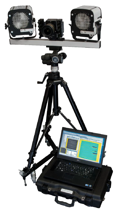
isi-sys offers timed thermal loading modules to to heat-up the objects of measurement.
A automated precise control of heat loading and a corresponding timed shearographic measurement is required to achieve a reproducible test procedure for non destructive testing experiments and automated systems.
Any conventional halogen flood lights with 220V can be connected. isi-sys recommends some flood lights used for professional photography. Thus they can be mounted on standard light stand of e. g. Manfrotto etc. and easily directed to the area of interest independent of the sensor head. Also this lights offer some choices of reflector combinations.
The start and duration of the heat loading and the measurements can be set per computer controlled timer, which permits reproducible sequences of the test process.
Vakuum Loading
The vacuum is another loading method for non destructive testing. The modular system concept allows to combine the SE2 sensor with different vacuum loading devices, which reduces system expense and keeps the equipment smart and mobile compared to other solutions .
The vacuum methods can be categorized depending on the loading principle into vacuum chambers/vacuum cabins and vacuum hood/vacuum windows.
Vacuum hood and Vacuum window
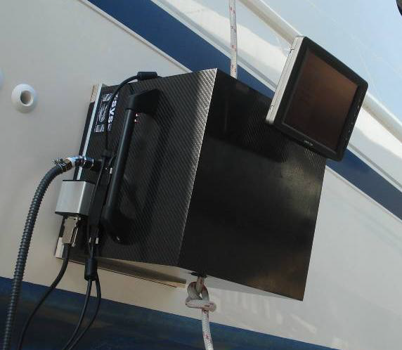 The vacuum hood is a modular extension accessories for the SE2 sensor. The sensor will be mounted inside of the hood and therfore the measurement area is covered from sun light influences.
The system has small dimensions and is for this reason very mobile and flexible, additionally the low required vacuum pump power is an advantage.
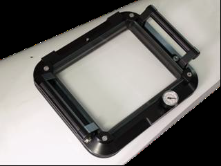
If you use the vacuum window, the sensor is outside the vacuum volume. The system is monitoring the object through the window. The bending forces are only across the field of view.
Due to the small volume of the vacuum window hood it can be used in combination with the small isi-vacuum unit (also used for isi-piezoshakers with vacuum cup adapter). The unit includes two separate vacuum pumps, where the second can be used for the vacuum suction cup tripod.
Vacuum chamber and Vacuum cabin
Generally vacuum chambers or cabins have the advantage against vacuum hoods and windows, that the forces appear uniform from all sides on the object. This avoids superposed fringes by global deformation such as by hood, where a bending force on the object surface is superposed, as usually the pressure forces are applied only in one direction on one side of the surface, where the hood is applied.
In both systems the sensor is inside the vacuum volume, which causes pressure loading also on the sensor. The camber and the cabin are bigger than the object and therefore depending on object size the mobility is restricted.
isi-sys offers the newly designed testing vacuum cabin based on aluminium-foam sandwich elements, which is recommended e. g. for frequently manual spot tests or laboratory use. Samples with a size up to 450 x 750 mm can be measured in this cabin.
Furthermore isi-sys GmbH cooperates with different manufacturer for large vacuum chambers.