Challenges
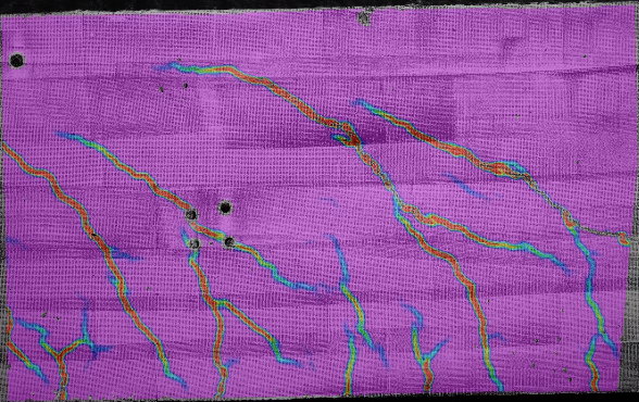
Assembled components typically have complex interactions with one another. Contact points can vary during operational cycles due to part movement. This means that the locations of peak strains can be hard to predict, and they are often not stationary. The movement of parts can also make it impractical to maintain electrical connections with gauges. Even when they are stationary and easy to locate, the highest strains can be concentrated in very small areas or have high gradients. Peak values may be lost to the averaging effect produced by gauges.
Solution
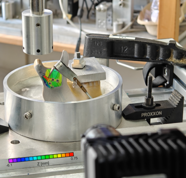
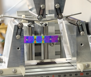
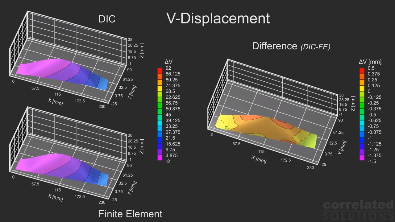
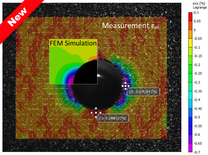
Vic-3D provided a means for making strain measurements across the entire profile of the gear tooth. Because it provides full-field measurements, it was not necessary to choose a particular point at which measurements would be made. This allowed the peak strains to be clearly visualized and accurately measured at various stages of the operational cycle. Vic-3D also measured displacement in three dimensions. This feature allowed our customer to recognize and quantify twisting of the gear tooth under load.